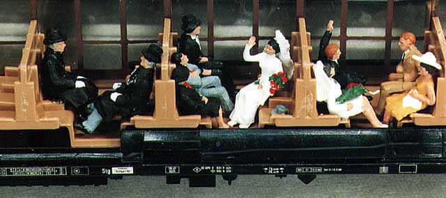
Digital Interior Lighting of Rail Cars
Once you decided to use digital systems on your model railway, you should employ this technology throughout. As opposed to analogue systems, the voltage on the rails of digital systems is nearly constant. This has the advantage to have the interior lights of passenger cars always at the same level of brightness. It used to really annoy me that the lighting appeared to have the intensity of gas lanterns during slow running of the trains. Conversely, due to Maerklins typical high voltage pulses of 24 volts during a change in direction, the virtual passengers would go blind at that time.
Since it can't always be night on a typical model railway setup, the model railroader should really be able to control the interior lights of cars. This is desirable even during "night operation", since cars parked in shunting yards are normally not lit. Further problems exist in "Schattenbahnhoefen" (shadow railway stations) where complete trains are hidden and wait to be used. Each control unit or booster can handle about 5 locomotives and an illuminated train requires as much power as a locomotive. New, expensive transformer / booster combinations might be required due to insufficient power. How to implement interior lighting that can be controlled?
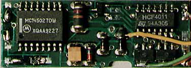
K73 is the magical word. This small decoder was originally developed to control M-track turnouts. Due to its size, this decoder is perfectly suited for our purposes. The only difference between k83 and k73 is in the number of magnetic items that can be controlled with the decoder. The k83 can control 4 solenoid accessories, the k73 only one.
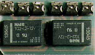
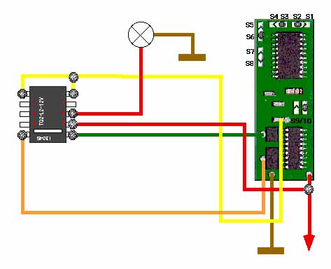
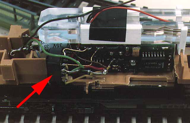
It is not possible to supply lighting power for the whole train through this one, small decoder. That is why we also need a small bi-stable relay with a minimum of one switching contact. If this can't be found, it is also possible to use the original Maerklin Universal Relay 7244 or the Viessmann relays 5551 /5552, as I have done. Since these parts are too large to build into a railcar, you need to de-solder one of the micro-relays. There are two one pole switch contacts and, when operated with DC there is also an automatic off switch in the end position. Since we only require a simple ON /OFF function, the connections should be done according to the diagram. To connect the relays properly, the imprint must be noticed (white bar down). The two upper pins are for the power supply, while the lower ones are connected to the coils. To the right and the left are two switching contacts, but since we just need a simple ON / Off function to control the interior lighting, we only require two of these contacts.
Most of the passenger cars from Maerklin can be equipped with short current-conducting couplers (7319) and thus it is not necessary to pull wires from one car to the next. I mounted two pick-up shoes underneath the car to assure good power take off. Even on long stretches with many turnouts, the lights are thus without flicker. Mind you, this car cannot be used on layouts with analogue and digital circuits, that have separators between the two types of circuits, since this would cause a short.
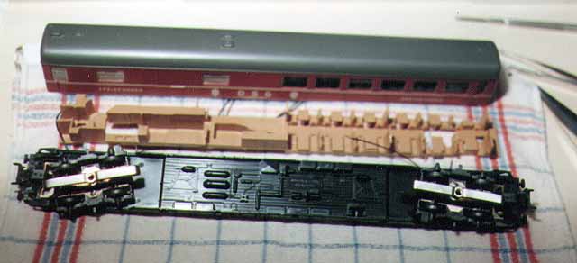
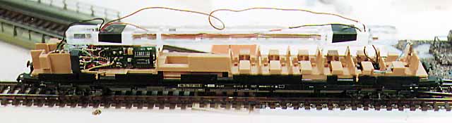
So that you can't see the k73 decoder through the windows of a passenger car, it should be placed in a baggage car. Alternatively you can place it in a sleeping car (with some of the windows blacked out) or in a dining car (kitchen area). Occasionally you might have to remove a part of the interior furnishings. It is easy to see on the photograph how small the relay is, compared to the k73 decoder.
To keep the k73 decoder small, Maerklin did not use dip-switches. Instead, the address needs to be set via 10 solder bridges. Depending on the desired address the correct contacts are connected. The settings for S1 to S8 are valid in the same way they are used for the k83 and k84 decoders. In addition, you find solder bridges for S9 and S10. Since a k73, as opposed to the k83 / k84, is only able to represent one address, instead of a group of four, these two bridges are used to specify the particular single address. I used the solder bridges S1 to S8 to represent the addresses 253-256 as follows:
| off, on, on, off, off, on, off, off |
After that it is necessary to define which individual address within the group of four is valid:
| address |
S9 |
S10 |
| 253 |
closed |
closed |
| 254 |
open |
closed |
| 255 |
closed |
open |
| 256 |
open |
open |
On purpose I took one of the highest addresses with 255, so as not to confuse it with the more common addresses for turnouts or signals.
One could, of course, also use the c96 decoder, but I think this has some disadvantages compared to the above solution:
The first would be the load capacity. The relays can be loaded up to 2000mA, whereas with the c96 it is limited to 200mA or 10%. It is possible though to use a maximum of three exits with the c96. Thus one could illuminate the "decoder car" through f1, the cars in front through f2 and the cars behind through f3. Since the current conducting couplers only have one pole, f4 cannot be used.
The second disadvantage is because one of the 80 locomotive addresses must be used with this type of decoder. If one requires several addresses for the interior lighting of cars, these special functions might no longer be available for locomotives with the 60901.
Normally a whole train is either lit or dark. It is less convenient to press three f-keys, than to just switch one k73.